12. Using a matrix to transform a point cloud
In this tutorial we will learn how to transform a point cloud using a 4x4 matrix. We will apply a rotation and a translation to a loaded point cloud and display then result.
This program is able to load one PCD or PLY file; apply a matrix transformation on it and display the original and transformed point cloud.
Contents
12.1. The code
First, create a file, let’s say, matrix_transform.cpp in your favorite
editor, and place the following code inside it:
12.2. The explanation
Now, let’s break down the code piece by piece.
We include all the headers we will make use of. #include <pcl/common/transforms.h> allows us to use pcl::transformPointCloud function.
This function display the help in case the user didn’t provide expected arguments.
We parse the arguments on the command line, either using -h or –help will display the help. This terminates the program
We look for .ply or .pcd filenames in the arguments. If not found; terminate the program. The bool file_is_pcd will help us choose between loading PCD or PLY file.
We now load the PCD/PLY file and check if the file was loaded successfully. Otherwise terminate the program.
This is a first approach to create a transformation. This will help you understand how transformation matrices work. We initialize a 4x4 matrix to identity;
    |  1  0  0  0  |
i = |  0  1  0  0  |
    |  0  0  1  0  |
    |  0  0  0  1  |
Note
The identity matrix is the equivalent of “1” when multiplying numbers; it changes nothing. It is a square matrix with ones on the main diagonal and zeros elsewhere.
This means no transformation (no rotation and no translation). We do not use the last row of the matrix.
The first 3 rows and columns (top left) components are the rotation matrix. The first 3 rows of the last column is the translation.
Here we defined a 45° (PI/4) rotation around the Z axis and a translation on the X axis. This is the transformation we just defined
    |  cos(θ) -sin(θ)  0.0 |
R = |  sin(θ)  cos(θ)  0.0 |
    |  0.0     0.0     1.0 |

t = < 2.5, 0.0, 0.0 >
This second approach is easier to understand and is less error prone. Be careful if you want to apply several rotations; rotations are not commutative ! This means than in most cases: rotA * rotB != rotB * rotA.
Now we apply this matrix on the point cloud source_cloud and we save the result in the newly created transformed_cloud.
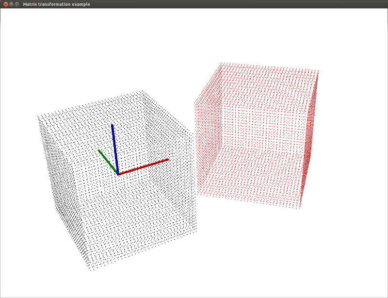
We then visualize the result using the PCLVisualizer. The original point cloud will be displayed white and the transformed one in red. The coordoniates axis will be displayed. We also set the background color of the visualizer and the point display size.
12.3. Compiling and running the program
Add the following lines to your CMakeLists.txt file:
After you have made the executable, run it passing a path to a PCD or PLY file. To reproduce the results shown below, you can download the cube.ply file:
$ ./matrix_transform cube.ply
You will see something similar to this:
./matrix_transform cube.ply
[pcl::PLYReader] /home/victor/cube.ply:12: property 'list uint8 uint32 vertex_indices' of element 'face' is not handled
Method #1: using a Matrix4f
 0.707107 -0.707107         0       2.5
 0.707107  0.707107         0         0
        0         0         1         0
        0         0         0         1

Method #2: using an Affine3f
 0.707107 -0.707107         0       2.5
 0.707107  0.707107         0         0
        0         0         1         0
        0         0         0         1

Point cloud colors :  white   = original point cloud
                       red    = transformed point cloud
12.4. More about transformations
We need a vector with 4 components. What do you put in the last component ? It depends on what you want to do:
- If you want to transform a point: put 1 at the end of the vector so that the translation is taken in account.
- If you want to transform the direction of a vector: put 0 at the end of the vector to ignore the translation.
Here’s a quick example, we want to transform the following vector:
[10, 5, 0, 3, 0, -1]
This is what you need to do to transform the vector:
[10, 5, 0,  1] * 4x4_transformation_matrix
[3,  0, -1, 0] * 4x4_transformation_matrix